Diferencia entre revisiones de «Led dual para cambio de región»
(alpha1) |
(a medio traducir con fotos) |
||
| Línea 1: | Línea 1: | ||
| − | + | Si has instalado un [Interruptor_para_cambiar_región_NTSC interruptor para cambio de región] en tu Gamecube, puede que quieras cambiar el led naranja, por uno de dos colores. En la instalación usaremos un interruptor DPDT (Double Pole, Double Throw). | |
| − | + | Led de dos colores pueden ser caros y con limitaciones en el color. Mmmonkey usó un led azul de 3.3v, y luego compró unos blanco de mismo del mismo volatje, al no poder encontrar otros por un precio razonable. No hay que elegir estos colores, pero si hay que asegurarse que ambos led tienen las mismas especificaciones (en nuestro caso LEDs de 3.3v 3mm). | |
| − | + | La teoría es simpe, tenemos que aplanar dos leds de 3mm, y pegarlos juntos. Mmonkeya usó papel de lija para aplanarlos (si tienes limas de agujas también se puede usar, aunque necesitará un poco de pegamento para acabar el trabajo). | |
| − | + | <center>[[Archivo:wikigcleds_gc-led-round.jpg|200px]] [[Archivo:wikigcleds_gc-led-flat.jpg|200px]]</center> | |
| − | |||
| − | + | Asegurate de no aplastarlo demasiado, y se cuidadoso de no lijar el interior del LED, al aplanar los dos, es recomendable conectarlos a una fuente de alimentación adecuada para comprobar que aún funcionan. Con el pegamentos, pégalos, asegurándote que las patas están bien conectadas (las patas del cátodo de cada LED deberían estar en línea, y luego las patas del ánodo deberían de estar de igual forma). Prueba a ponerlo en la consola, y si no cabe entra, ten cuidado al lijarlo un poco. Debería de entrar sin problemas. | |
| + | |||
| + | <center>[[Archivo:wikigcleds_gc-led-glue.jpg|200px]] [[Archivo:wikigcleds_gc-led-test-fit.jpg|200px]]</center> | ||
| + | <center>Pegados y testeados</center> | ||
| + | |||
| + | |||
| + | Mmmonkey no podía resistirse a probarlos para ver como se iluminan. | ||
| + | |||
| + | <center>[[Archivo:wikigcleds_gc-led-white.jpg|200px]] [[Archivo:wikigcleds_gc-led-blue.jpg|200px]]</center> | ||
| + | |||
| + | |||
| + | Ahora quita el LED que trae, prestando atención a su orientación (el cátodo/pata negativa está a la izquierda cuando se ve de frente) | ||
| − | |||
| − | |||
Now remove the existing LED, making note of its orientation (the cathode/negative leg is on the left as you're looking at the front of the console). Obviously it's a lot easier to remove the old LED using a de-soldering pump or braid. | Now remove the existing LED, making note of its orientation (the cathode/negative leg is on the left as you're looking at the front of the console). Obviously it's a lot easier to remove the old LED using a de-soldering pump or braid. | ||
| − | + | <center>[[Archivo:wikigcleds_gc-led-test2.jpg|200px]] [[Archivo:wikigcleds_gc-led-removed.jpg|200px]]</center> | |
| + | |||
First thing to do is to check the new LED for the Cathode (negative) leg (you can look inside the LED and see it's the larger piece of metal), carefully look at the first photo below and cut the first negative leg, bend and solder it to the other negative leg. | First thing to do is to check the new LED for the Cathode (negative) leg (you can look inside the LED and see it's the larger piece of metal), carefully look at the first photo below and cut the first negative leg, bend and solder it to the other negative leg. | ||
Cut one of the negative legs Then bend and solder it to the other negative leg | Cut one of the negative legs Then bend and solder it to the other negative leg | ||
| + | |||
| + | <center>[[Archivo:wikigcleds_gc-led-cut-neg.jpg|200px]] [[Archivo:wikigcleds_gc-led-sold-neg.jpg|200px]]</center> | ||
| + | |||
Now bend the single remaining negative leg, comparing it to the original LED to make sure you have the bend in the correct place. Look carefully at the photos below and bend one of the positive legs as close to the plastic of the LED as you can, then trim all the legs (don't trim them too short, you'll cut them to length after soldering into place). | Now bend the single remaining negative leg, comparing it to the original LED to make sure you have the bend in the correct place. Look carefully at the photos below and bend one of the positive legs as close to the plastic of the LED as you can, then trim all the legs (don't trim them too short, you'll cut them to length after soldering into place). | ||
| + | |||
| + | <center>[[Archivo:wikigcleds_gc-led-bend1.jpg|200px]] [[Archivo:wikigcleds_gc-led-bend2.jpg|200px]]</center> | ||
Bend the remaining negative leg Bend and trim the positive legs | Bend the remaining negative leg Bend and trim the positive legs | ||
| Línea 29: | Línea 43: | ||
When this new LED is fitted to the console, only the single negative leg will actually go through the circuit board and be soldered into the same place as the old LED. The two positive legs should fit with one coming straight down the front of the circuit board, and the other bent so it is sticking out the back of the circuit board. Test fit the LED, making sure that you have the positive and negative around the correct way, mmmonkey found the following a nice fit. | When this new LED is fitted to the console, only the single negative leg will actually go through the circuit board and be soldered into the same place as the old LED. The two positive legs should fit with one coming straight down the front of the circuit board, and the other bent so it is sticking out the back of the circuit board. Test fit the LED, making sure that you have the positive and negative around the correct way, mmmonkey found the following a nice fit. | ||
| − | + | <center>[[Archivo:wikigcleds_gc-led-test1.jpg|200px]] [[Archivo:wikigcleds_gc-led-test2.jpg|200px]]</center> | |
| + | |||
Now you'll need some wire to link up the LED to the switch at the rear of the console. You'll need three pieces of wire, one to carry the power to the switch, and another two for each positive leg, mmmonkey used some IDE cable, strip the ends of the wires and tin them by melting a small amount of solder to them. Leave one of the wires longer to reach the positive leg coming straight down the front of the circuit panel. | Now you'll need some wire to link up the LED to the switch at the rear of the console. You'll need three pieces of wire, one to carry the power to the switch, and another two for each positive leg, mmmonkey used some IDE cable, strip the ends of the wires and tin them by melting a small amount of solder to them. Leave one of the wires longer to reach the positive leg coming straight down the front of the circuit panel. | ||
| − | IDE | + | <center>[[Archivo:wikigcleds_gc-led-wires.jpg|200px]]</center> |
| + | <center>Cable IDE preparado para ser soldado al LED</center> | ||
| − | + | ||
| + | Suelda un cable (el cable central si tu usas un cable IDE) donde el LED original tomama la energía, luego aislalo para evitar cortocicuitos. Asegurate que con el asiamiento, no se tapa el agujero de la endidura de la pata negativa. | ||
| + | |||
| + | <center>[[Archivo:wikigcleds_gc-led-power.jpg|200px]] [[Archivo:wikigcleds_gc-led-ins.jpg|200px]]</center> | ||
Power wire soldered into place Power wire insulated | Power wire soldered into place Power wire insulated | ||
| + | |||
Now solder the LED into place, solder the negative leg into where the original LED's negative leg was and carefully trim the excess off, then solder the remaining leads to the positive legs of the LED, again - carefully trim the legs if needed. mmmonkey would probably try soldering the wires before putting the LED in place next time, the front positive LEG was awkward! | Now solder the LED into place, solder the negative leg into where the original LED's negative leg was and carefully trim the excess off, then solder the remaining leads to the positive legs of the LED, again - carefully trim the legs if needed. mmmonkey would probably try soldering the wires before putting the LED in place next time, the front positive LEG was awkward! | ||
| + | |||
| + | <center>[[Archivo:wikigcleds_gc-led-pos2.jpg|200px]] [[Archivo:wikigcleds_gc-led-pos1.jpg|200px]]</center> | ||
| + | |||
Rear positive leg soldered Front positive leg soldered | Rear positive leg soldered Front positive leg soldered | ||
| − | + | Ahora lleva los cables sobre la selección del selector de región, suelda el cable de energía al contacto central de la fila de repuestos del interruptor, luego sueda el resto de cables a los contactor superior, e inferior. | |
| + | |||
| + | <center>[[Archivo:wikigcleds_gc-led-switch.jpg|200px]]</center> | ||
| + | |||
| − | |||
| − | + | Esto es todo, arma tu Gamecube, y asegurate de no atrapar los cables. | |
| − | + | Mmmonkey tuvo dificultades para conseguir un LED azul para las fotos, a continuación puedes ver los intentos por ver los diferentes colores del LED: | |
| + | #Blanco para modo JPN. | ||
| + | #Azul para modo USA. | ||
| − | + | to show up blue on a digital camera, below are attempts to show the different colours of the LED (white for JPN mode, blue for USA mode). | |
| − | + | <gallery> | |
| + | File:wikigcleds_gc-led-white2.jpg|LED blanco para modo japonés. | ||
| + | File:wikigcleds_gc-led-blue2.jpg|LED Azul para modo USA. | ||
| + | File:wikigcleds_gc-led-white3.jpg|LED blanco para modo japonés (2). | ||
| + | File:wikigcleds_gc-led-blue3.jpg|LED Azul para modo USA. (2) | ||
| + | </gallery> | ||
Revisión del 22:22 16 abr 2014
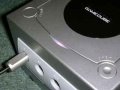
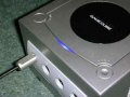
Si has instalado un [Interruptor_para_cambiar_región_NTSC interruptor para cambio de región] en tu Gamecube, puede que quieras cambiar el led naranja, por uno de dos colores. En la instalación usaremos un interruptor DPDT (Double Pole, Double Throw).
Led de dos colores pueden ser caros y con limitaciones en el color. Mmmonkey usó un led azul de 3.3v, y luego compró unos blanco de mismo del mismo volatje, al no poder encontrar otros por un precio razonable. No hay que elegir estos colores, pero si hay que asegurarse que ambos led tienen las mismas especificaciones (en nuestro caso LEDs de 3.3v 3mm).
La teoría es simpe, tenemos que aplanar dos leds de 3mm, y pegarlos juntos. Mmonkeya usó papel de lija para aplanarlos (si tienes limas de agujas también se puede usar, aunque necesitará un poco de pegamento para acabar el trabajo).


Asegurate de no aplastarlo demasiado, y se cuidadoso de no lijar el interior del LED, al aplanar los dos, es recomendable conectarlos a una fuente de alimentación adecuada para comprobar que aún funcionan. Con el pegamentos, pégalos, asegurándote que las patas están bien conectadas (las patas del cátodo de cada LED deberían estar en línea, y luego las patas del ánodo deberían de estar de igual forma). Prueba a ponerlo en la consola, y si no cabe entra, ten cuidado al lijarlo un poco. Debería de entrar sin problemas.


Mmmonkey no podía resistirse a probarlos para ver como se iluminan.


Ahora quita el LED que trae, prestando atención a su orientación (el cátodo/pata negativa está a la izquierda cuando se ve de frente)
Now remove the existing LED, making note of its orientation (the cathode/negative leg is on the left as you're looking at the front of the console). Obviously it's a lot easier to remove the old LED using a de-soldering pump or braid.


First thing to do is to check the new LED for the Cathode (negative) leg (you can look inside the LED and see it's the larger piece of metal), carefully look at the first photo below and cut the first negative leg, bend and solder it to the other negative leg.
Cut one of the negative legs Then bend and solder it to the other negative leg


Now bend the single remaining negative leg, comparing it to the original LED to make sure you have the bend in the correct place. Look carefully at the photos below and bend one of the positive legs as close to the plastic of the LED as you can, then trim all the legs (don't trim them too short, you'll cut them to length after soldering into place).


Bend the remaining negative leg Bend and trim the positive legs
When this new LED is fitted to the console, only the single negative leg will actually go through the circuit board and be soldered into the same place as the old LED. The two positive legs should fit with one coming straight down the front of the circuit board, and the other bent so it is sticking out the back of the circuit board. Test fit the LED, making sure that you have the positive and negative around the correct way, mmmonkey found the following a nice fit.

Now you'll need some wire to link up the LED to the switch at the rear of the console. You'll need three pieces of wire, one to carry the power to the switch, and another two for each positive leg, mmmonkey used some IDE cable, strip the ends of the wires and tin them by melting a small amount of solder to them. Leave one of the wires longer to reach the positive leg coming straight down the front of the circuit panel.

Suelda un cable (el cable central si tu usas un cable IDE) donde el LED original tomama la energía, luego aislalo para evitar cortocicuitos. Asegurate que con el asiamiento, no se tapa el agujero de la endidura de la pata negativa.


Power wire soldered into place Power wire insulated
Now solder the LED into place, solder the negative leg into where the original LED's negative leg was and carefully trim the excess off, then solder the remaining leads to the positive legs of the LED, again - carefully trim the legs if needed. mmmonkey would probably try soldering the wires before putting the LED in place next time, the front positive LEG was awkward!


Rear positive leg soldered Front positive leg soldered
Ahora lleva los cables sobre la selección del selector de región, suelda el cable de energía al contacto central de la fila de repuestos del interruptor, luego sueda el resto de cables a los contactor superior, e inferior.

Esto es todo, arma tu Gamecube, y asegurate de no atrapar los cables.
Mmmonkey tuvo dificultades para conseguir un LED azul para las fotos, a continuación puedes ver los intentos por ver los diferentes colores del LED:
- Blanco para modo JPN.
- Azul para modo USA.
to show up blue on a digital camera, below are attempts to show the different colours of the LED (white for JPN mode, blue for USA mode).
LED blanco para modo japonés.
LED Azul para modo USA.
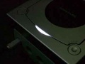
LED blanco para modo japonés (2).
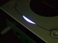
LED Azul para modo USA. (2)


